11
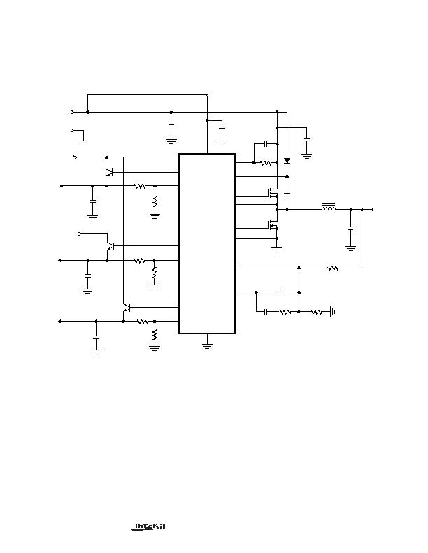
ISL6432 DC-DC Converter Application Circuit
Figure 8 shows an application circuit. For detailed information
on the circuit, including a Bill-of-Materials and circuit board
description, please refer to the Power Management Home
Gateway section on Intersils web page (www.intersil.com)
GND
VCC
+5V
PGND
LGATE
UGATE
OCSET
PHASE
FB
COMP
V
OUT2
FB2
DRIVE2
Q3
DRIVE3
FB3
DRIVE4
C2
V
OUT3
V
OUT4
C10
C9
ISL6432
Q4
L2
+
+
+
+
C4
C1
C6
C5
R1
V
OUT1
R6
C14
C3
1000?/SPAN>F
1000?/SPAN>F
C8
330?/SPAN>F
1?/SPAN>F
1?/SPAN>F
1000pF
2.5?/SPAN>H
10pF
22nF
1.50K
GND
(2.5V)
(1.8V)
(1.5V)
FB4
+3.3V
IN
R8
698
R7
45.3K
12K
Q5
U1
1
2
13
14
5
15
16
4
3
12
9
10
6
8
11
(2.5V)
FIGURE 8. POWER SUPPLY APPLICATION CIRCUIT FOR A MICROPROCESSOR COMPUTER SYSTEM
Q1,2
HUF76129D3S
+3.3V
FZT649
2SD1802
2SD1802
+
R3
R2
5.90K
12.7K
R5
R4
9.09K
7.15K
R10
R9
7.50K
8.45K
BOOT
7
C7
0.47?/SPAN>F
D1
MA732
ISL6432
发布紧急采购,3分钟左右您将得到回复。
相关PDF资料
ISL6521CBZS2698
IC REG QD BCK/LINEAR 16-SOIC
ISL6528CBZ-TS2698
IC REG DL BCK/LINEAR SYNC 8-SOIC
ISL6529CBZ
IC REG DL BCK/LINEAR SYNC 14SOIC
ISL6534CVZ-TR5229
IC REG 3OUT BCK/LINEAR 24EPTSSOP
ISL6549CRZR5213
IC REG DL BCK/LINEAR SYNC 16-QFN
ISL9305IRTHWLNCZ-T
IC REG QD BUCK/LINEAR 16TQFN
ISL9305IRTWLNCZ-T
IC REG QD BUCK/LINEAR 16TQFN
ISL9307IRTWCWNZ-T
IC REG QD BCK/LINEAR SYNC 16TQFN
相关代理商/技术参数
ISL6433BCB
制造商:Intersil Corporation 功能描述:
ISL6434CB
制造商:Intersil Corporation 功能描述:
ISL6435CA
制造商:Intersil Corporation 功能描述:
ISL6436HIB
制造商:Intersil Corporation 功能描述:
ISL6436LIB
功能描述:IC CTRLR PS USB DUAL PORT 8-SOIC RoHS:否 类别:集成电路 (IC) >> 接口 - 控制器 系列:- 标准包装:4,900 系列:- 控制器类型:USB 2.0 控制器 接口:串行 电源电压:3 V ~ 3.6 V 电流 - 电源:135mA 工作温度:0°C ~ 70°C 安装类型:表面贴装 封装/外壳:36-VFQFN 裸露焊盘 供应商设备封装:36-QFN(6x6) 包装:* 其它名称:Q6396337A
ISL6439ACB
制造商:Rochester Electronics LLC 功能描述:- Bulk 制造商:Intersil Corporation 功能描述:
ISL6439ACB-T
制造商:Rochester Electronics LLC 功能描述:- Bulk 制造商:Intersil Corporation 功能描述:
ISL6439ACR
制造商:Rochester Electronics LLC 功能描述:- Bulk 制造商:Intersil Corporation 功能描述: